Wednesday, December 28, 2016
Wednesday, December 21, 2016
Wednesday, December 14, 2016
Week 15: Finals, Winter Break Plans
As of the writing of this post, regular scheduled classes have ended and final exams have begun. No work is currently being done on the bender, due to rearranging tools and machines at home and preparation for final exams, so no update to show here. The tank desk mentioned before can be seen below, but it was disassembled for transport and has been placed to the side for the moment as things are being rearranged.
I will not be at home to perform any work on the bender for the majority of winter break, which will be from December 21st to January 24th. As of this post, I am unsure of the exact date at which I will return. I believe that the capabilities demonstrated thus far are proof enough that we have completed our task as requested of us, but that variables yet left undetermined (such as the decision between 5052 and 6061 aluminum) should be resolved before more work is performed, mainly due to the significant impact that such a decision would have on the work to be performed. In the particular example given, if 5052 aluminum were indeed to be utilized, then calculations made thus far would have to be redone and work thus far would be null and void.
Regarding work provided by other teams, contact has been made with the vehicle positioning sensing subteam with concern to the potential for fabrication of a corrugated metal strip to be used with a Hall effect sensor. Extra details revealed the precision required for the metal strip, and having not received information early enough to warrant serious investigation, it was decided that the best course of action would be to move forward with external fabrication of the corrugated strip. Internal investigation of corrugated strip creation will be pursued during the spring semester if extra time is available
What a tank desk looks like when set up:

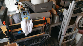
What the tank desk look like right now, with things being shuffled around:
I will not be at home to perform any work on the bender for the majority of winter break, which will be from December 21st to January 24th. As of this post, I am unsure of the exact date at which I will return. I believe that the capabilities demonstrated thus far are proof enough that we have completed our task as requested of us, but that variables yet left undetermined (such as the decision between 5052 and 6061 aluminum) should be resolved before more work is performed, mainly due to the significant impact that such a decision would have on the work to be performed. In the particular example given, if 5052 aluminum were indeed to be utilized, then calculations made thus far would have to be redone and work thus far would be null and void.
Regarding work provided by other teams, contact has been made with the vehicle positioning sensing subteam with concern to the potential for fabrication of a corrugated metal strip to be used with a Hall effect sensor. Extra details revealed the precision required for the metal strip, and having not received information early enough to warrant serious investigation, it was decided that the best course of action would be to move forward with external fabrication of the corrugated strip. Internal investigation of corrugated strip creation will be pursued during the spring semester if extra time is available
What a tank desk looks like when set up:

What the tank desk look like right now, with things being shuffled around:

Wednesday, December 7, 2016
Week 14: Alternative Bender Table, Future Plans
The main focus for work was, as mentioned in the group post for
the week, on the final report, third writing assignment, and final
presentation. The past six weeks of the build have seen a personal input of 20+
hours per week, which combined with the required input for other courses
appeared to have led to accumulated levels of fatigue. During the coming winter
break, limited work will be performed as I will not be at home for the majority
of the duration. However, work completed thus far has provided positive results
that will lead the way for what will need to be done next semester, which was
the main goal of work this semester.
Some searching was done during the semester for desks,
stands, or mounts that the bender could be placed on for permanent installment
in the Spartan Superway shop. Towards this end, it was originally conceived
that a desk would be constructed from two unused table legs, 2”x4”s, plywood,
and bolts, nuts, and screws. However, searching on Craigslist for free desks
revealed several promising alternatives, including a “tank desk.” A “tank desk”
was acquired in decent condition this past weekend, so it will be tested as the
desk of choice for the first table to mount the bender upon.
Wednesday, November 30, 2016
Week 13: Final Report, Third Presentation
The third presentation and final report rough draft were the
focus this past week, and will continue to be so throughout the week, and possibly
next weekend as well. Owing to Thanksgivings break and not being in town, no
work was done on the bender this week. However, as stated last week, bender
results that matched expectations gave great confidence that the work that we
have done thus far is going in the direction we need it to. Therefore, it seems
that we have overcome the greatest obstacle in our path, which was the creation
of a proper die to produce results exactly as we needed them.
The track improvement team has provided the team with some
updated information, as well as their expectations for next semester. They
informed us that they intended for us to create the corners for the improved
track, but were considering reusing the station sections from the previous
year. It so happens that work on the corner sections (in terms of dies) has progressed
the furthest, which is beneficial for us. Additionally, corner sections were
assumed to be potentially the most troublesome, given the bender type. Comparatively,
bends for the station sections are seen as simply smaller versions of the full
corner bends that were prepared for and tested, so all signs on work performed thus
far are positive.
Wednesday, November 23, 2016
Week 12: More Positive Results, Foreseeable Future
Recent work includes the creation of one finalized die with radius and arc angle calculated from equation addressing material springback and wanted dimensions for the final track. The bender was able to reliably and repeatedly bend around the die, producing very uniform results. New holes had to be drilled in the aluminum baseplate, both for the die and for the material hold block as well.
The results produced by the bender confirmed that all calculations used are true representations of what to actually expect. This is significant because it means that every other final die that is made according to calculated numbers should work exactly as planned, so work will proceed in that direction.
Less time was spent working on the project this weekend, owing mainly to accumulated fatigue (and lightheadedness on one of the days).

This particular die was for the top corner rail,
with the intent of creating the corner bend in one go.

The baseplate was drilled for the die and material
hold block. All parts are ready to go in this pic.
And it was raining outside.

The first bend from the die was just about 90 degrees
(matching the concrete lines on the floor) and at the
radius intended. Couldn't have gone better, and
successive bends had the same results.
Tuesday, November 15, 2016
Week 11: Somewhat Positive Results, Work Still Needed
Utilization of the wheel on the bender arm worked as planned, producing the curve that was shown in last week's post. Upon using the wheel to bend a second piece of test material this last weekend, the bender failed to produce the same result. Investigation revealed that the 5/16" bolt used to hold the wheel in place was not strong enough, and had deformed due to the shear stress applied. A 3/8" bolt was subsequently tested, and subsequently failed as well. A simple design using 3/4" aluminum bar stock instead of a bolt, and 2" aluminum bar stock instead of a wheel fared better, resisting the shear force applied. Interestingly enough, the plywood die did not appear to deform in shape in spite of the loads applied.
Free, sturdy table legs were acquired over the weekend, and plans have been made to create a table for the bender for the Spartan Superway workshop. The table will be made '2x4's and aluminum diamond plate or plywood (all of which was free), along with some bolts purchased from the local hardware store (Lowes).
As a side note, the bill of materials for the project was due on November 15th. The many materials used in the build thus far have been free or have been scrap left over from previous years. Owning the many tools used and doing the work myself, labor and tooling costs are zero. As things currently stand, the cost for our material bender may be no more than the nuts, bolts, and washers that are used to hold everything together. This would be a large win for the Superway project, without even needing to calculate what would have been the comparative cost had the work been done externally.

Taken during the actual bending of material.

Comparison pictures of a sketched radius and actual bent material.
The match is fairly close, need to ensure a total 90* bend.

See above picture.

Bent bolt after material bend.

Table legs, to be used for Spartan Superway workbench.

Dies made thus far.

Replacement roller, with 3/4" aluminum bar stock.
Required new holes in the aluminum bar.
Wednesday, November 9, 2016
Week 10: Work Revision, But Progress As Planned
Work continues on the build of the bender and necessary
dies. Utilization of a sample die and bending of material by hand resulted in a
bend very close to what calculations determined, being 10.4” radius die for a
20” radius bend of 6061 aluminum flat stock of 1.5” by 0.25”. The main work
completed this weekend included the manual bend of material as proof of concept
and verification of calculations, the viability of the current design, and that
work yet continues according to plan.
There is a general update to the specific tasks listed on
the Gantt chart, resulting from realizations during the build process. Instead
of planning for two separate builds for benders and die creation in between,
work will be put towards utilizing the single design made thus far, with an
emphasis on die revision as necessary.
Looking forward to bender use in the Spartan Superway workshop
(away from my home, where I am currently working on it), a means of support
will be required. At present, the bender sits atop an old lathe stand, which
has both the size and the weight to accommodate the forces applied to it, and
resist movement. The lathe stand was obtained with the intent for personal use,
so an alternative support will be investigated for permanent installment in the
Spartan Superway workshop.

The bend on the 1:1 die, resulting in a radius too large to be useful.

Size of the die (10.3") according to calculations to match the 20" radius.

The material bent on the 10.3" die compared to the 20" radius.

The 10.3" die attached to the table, with holding block clamped.

Milling flat of the aluminum holding block.

Reaming of the aluminum block hole after drilling.

The aluminum block bolted to the table with corresponding pin.

Some of the many drill bits used thus far, as well as calipers.
Wednesday, November 2, 2016
Week 9: Prototype Problems, Course of Action
The group presentation can be seen in the week eight post for the group. As was calculated and shown in the presentation, the current bend radius should have been much too large to create a permanent bend as intended and necessary. The results were confirmed when the material was bent around the radius by hand, with minimal permanent bending occurring. The calculated radius for a 20" bend was found to be 10.4" for the die, which will be attempted this coming weekend. The overall design of the bender has yet to be disproved, however. This past week, less effort was put towards the project, owing to obligations for other courses, including test preparation.


The die, with a radius of approximately 20".

Material after having been forced about the die.
Wednesday, October 26, 2016
Week 8: Presentation 2, Prototype Progress
The second wave of presentations was today, and much of the progress can be seen in the group presentation in the main blog post. Materials have in large part been taken from the Spartan Superway fabrication shop, with the few materials having been purchased so far including cast iron casters, steel bolts, and corresponding washers and nuts. The prototype is currently being built atop an old lathe stand as a temporary base, as the size and weight of it are useful for resisting the applied forces from the bender.


Wednesday, October 19, 2016
Week 7: Materials, Design Maturation
The design for the rapid prototype has been reverted towards
the original design in lieu of a Hossfeld bender, in light of material
acquisition, available support options, and details from the track improvement
team. Further revisions will be made as necessary with concerns towards the
final design.
Since last week’s post, additional materials have been gathered
from the Spartan Superway shop and sourced from local hardware stores for the
build. An old lathe stand will be used as a temporary base, as its size and
weight appear to be sufficient for the moment. A more permanent stand for
placement in the Spartan Superway shop will require additional research at a
later date.
In more specific detail:
A cast
iron wheel from a caster will be used on the arm to push against the material.
The arm
may be one of several pieces, either solid rectangular aluminum or tube steel.
The die
will be cut from plywood, with metal banding added if it proves too malleable.
Pins
and the center pivot will be made from either aluminum or steel bar stock.
The square
block to hold the material will be made from square aluminum stock.
3/8” or
½” shoulder bolts will be used to bolt the bender to the lathe stand.
Large diamond
plate, aluminum plate, or plywood will be used to bridge the lathe stand
plates.


Wednesday, October 12, 2016
Week 6: Bender Redesign, Need Numbers
The original bender idea has been thrown out completely.
Imbalanced forces and unique pieces increase the liability of something
breaking, especially in the future where users may assume the system is more
robust than it actually is and treat it as such.
Therefore, the focus will now be on replicating a Hossfeld
bender or a design very similar to it. The overall simplicity of the design,
and the versatility provided by the pin positions, clamping blocks, and die
size should be more than sufficient for the needs of the project. The image of
the Hossfeld we will attempt to emulate, and the key components identified are
below. Die size, the main determinator of our bender’s output, will depend on
the final numbers from the track improvement team. The current 18” or 20”
radius necessary invalidates a die 1:1 in size, so curves will have to be bent in
individual sections.


Tuesday, October 4, 2016
Week 5: Redesign Details, Bender Rework?
As of the writing of this post, access to on-campus labs has
not yet been granted. Work with the track improvement, bogie design, and other
teams continue, and final dimensions of the bender have not yet been
determined. Initial information from the track improvement team suggests that
the radius used will be similar to the largest radius of the track developed
last year, which may ease production as having a larger radius will mean that
the material may require less force to manipulate. There’s been no new information
yet on the radius required for the section of track that constitutes the
station, more specifically about whether the dimensions are different or the
same compared to what was used previously.
An initial idea for a bender setup was detailed in last week’s
post, but evaluation of that design yet continues. Unbalanced forces may prove
troublesome over time, so the current thought is to replace the arm with a
proper Y-shaped arm, resulting in a design much more similar to a Hossfeld than
the original. The base plate may remain the same, unless the bolts/cylinders
affixed to it cannot be kept strictly vertical. In either case, the Hossfeld design
appears to be much more simple than the DiAcro design, in large part due to the
acceptable tolerances on the arms when compared to the circular shape and
chain/gear utilized by the DiAcro design. Expect more definite information next
week, as prototyping is scheduled to start in short order.
Wednesday, September 28, 2016
Week 4: Initial Bender Idea, Shop Access
I
have created a basic Solidworks model of what our Hossfeld-type bender may look
like. It consists of an arm that has a pin that rotates about a center pivot, a
base with a pin and the aforementioned center pivot, and a die that sits on the
center pivot and allows material to be bent across/around it.
The
dimensions of the bender, and more specifically the die, will largely depend
upon dimensions determined by the track improvement team for the next
generation track.
The
first prototype will most likely be created out of wood (plywood or hardwood)
with a metal band on the edge of the die and metal pins, though this is still
being debated. The final build should be made of mostly or entirely metal. The
intent is to make use of material currently sitting in the shop to fabricate
these benders before purchasing more material.

Tuesday, September 20, 2016
Week 3: Research and Ideas
Some research was done into stock benders, and most affordable methods appear to require force generated by the user to bend the stock.
One method appears to utilize a moment arm, and to force stock to bend about a pin at a pivot point, with force being applied at two points away from the fulcrum.
An alternative method appears to utilize a hydraulic ram/press with a mold or die to force material into shape.
A third method may utilize a scissor jack with a mold or die on one side to force material into shape.
Dies cast to particular specs appear to be expensive, so fabrication of molds in-house will be investigated.
The most pressing issue with the designs above is that they do not actively measure how much material has been bent.
A fourth method may work similarly to the first, but utilize a pawl on a large pivot pin and two ratchets (one to advance the pawl, one to hold the pawl in place while the other is moved) to allow for measured material advancement through the bender.
Rough sketches:


Wednesday, September 14, 2016
Week 2: Looking Back and Looking Forward
As is mentioned in the team's post this week, there are a number of things that can be done going forward, including determining working fabrication tools, contacting individuals, and looking at what work has been done on the project in the past. Here, I will address a few of those points in more detail below.
In the shop where the project is currently being housed, there are many hand tools and power tools available, but several tools do not appear to be in working order:
1) Such is the case for the band saws (one has a broken shaft (?), the other has a broken guide or some other ailment), and we are looking at having one fixed in the near future.
2) The lathe in the back of the room has apparently been unused for a year or more, and nobody is sure if it works or not. Tests will have to be carried out to determine its usability.
3) There is a mill against one of the walls, but with no power cord nearby, I could not see if it ran last week. Will look into it more this week.
Between last week and now, I have contacted two people who have worked with the Spartan Superway project before, Kyle Meininger and Kenny Strickland. Kyle runs SJSU's central workshop, and has helped fabricate parts for the project in the past. He gave me a tour of the shop, and offered to review or aid any fabrication methods or designs we may create. Kenny worked on the small-scale track during the 2015-2016 year, and he was able to give me some general information about it first-hand, and several points which I will detail below.
1) Methods for track change at stations presented a major problem. Barcodes were dirtied, the bogie passed by too fast to read it, or the physical support for the barcode reader mounted to the bogie broke. Magnets for one reason or another did not seem to work either.
2) Some designs were needlessly over-machined, such as curvature when creating blocks to hold the wheels to the bogies. Simplifications could be made to the design.
3) Due to the thin width of the top rail, bogies were not always forced to travel in the expected paths which provided them the space to fall of the track, especially at some of corners.
4) Bogies would occasionally stop for seemingly no reason after traveling several loops successfully. Teams were unsure whether it was a software issue or hardware issue.
5) Very little tolerance for error was incorporated into the design. For example, the vertical height between the top guide rail and side tracks that the bogie wheels rolled on mandated very specific heights and widths, which were not always met. Additionally, a change to the design of the front ends of the bogies made it such that there were clearance issues when approaching track changes.
Lastly, I will investigate access to fabrication capabilities beyond the project's shop. This will include several workshops on the SJSU campus, the Tech Shop one block away from campus, and possibly several individuals that have their own private workshops.
I will look to add pictures in the coming days to highlight several of the issues above.
See the week 3 post by the team for the images.
In the shop where the project is currently being housed, there are many hand tools and power tools available, but several tools do not appear to be in working order:
1) Such is the case for the band saws (one has a broken shaft (?), the other has a broken guide or some other ailment), and we are looking at having one fixed in the near future.
2) The lathe in the back of the room has apparently been unused for a year or more, and nobody is sure if it works or not. Tests will have to be carried out to determine its usability.
3) There is a mill against one of the walls, but with no power cord nearby, I could not see if it ran last week. Will look into it more this week.
Between last week and now, I have contacted two people who have worked with the Spartan Superway project before, Kyle Meininger and Kenny Strickland. Kyle runs SJSU's central workshop, and has helped fabricate parts for the project in the past. He gave me a tour of the shop, and offered to review or aid any fabrication methods or designs we may create. Kenny worked on the small-scale track during the 2015-2016 year, and he was able to give me some general information about it first-hand, and several points which I will detail below.
1) Methods for track change at stations presented a major problem. Barcodes were dirtied, the bogie passed by too fast to read it, or the physical support for the barcode reader mounted to the bogie broke. Magnets for one reason or another did not seem to work either.
2) Some designs were needlessly over-machined, such as curvature when creating blocks to hold the wheels to the bogies. Simplifications could be made to the design.
3) Due to the thin width of the top rail, bogies were not always forced to travel in the expected paths which provided them the space to fall of the track, especially at some of corners.
4) Bogies would occasionally stop for seemingly no reason after traveling several loops successfully. Teams were unsure whether it was a software issue or hardware issue.
5) Very little tolerance for error was incorporated into the design. For example, the vertical height between the top guide rail and side tracks that the bogie wheels rolled on mandated very specific heights and widths, which were not always met. Additionally, a change to the design of the front ends of the bogies made it such that there were clearance issues when approaching track changes.
Lastly, I will investigate access to fabrication capabilities beyond the project's shop. This will include several workshops on the SJSU campus, the Tech Shop one block away from campus, and possibly several individuals that have their own private workshops.
See the week 3 post by the team for the images.
Monday, August 29, 2016
Week 1: Let's Get Started
The track manufacturing and process development team for the 1/12 scale model is a new team starting this year, and determining what needs to be focused on from the get-go is not yet entirely clear. However, several issues appear to stand out, according to accounts from teams working on the model from last year. Investigating potential changes by the bogie and track improvement teams and working alongside them to aid in a better potential track design will be paramount, and will most certainly provide direction for the track manufacturing team.
Certain sections of track were created by an external company (Vanderbend), and other sections of track were created in-house, leading to discrepancies and unequal end product which did not allow for uniform functionality of pod cars. We are to devise an in-house method for fabrication, or standardize methods to be outsourced.
Availability of stock for the project, and common means for its manipulation for use, shall be investigated. Additionally, any specialized processes, tools, or training that may be required to aid in fabrication shall be pursued.
Frequent discussion between teams will be encouraged to ensure pertinent details are shared and that each team has meaningful input to aid in the overall design.
Assessment of the bogie design and track design changes, and evaluation possible methods of fabrication for the planned designs this year are forthcoming. Assessment of available in-house equipment to enable support beyond the end of my time working on the project will aid those that follow in my footsteps.
Records of any fabrication methods will be used to aid in documentation for the eventual hand-off of the task. Ensuring that detailed instructions are provided for every process so processes can be replicated precisely will be helpful.
Some issues concerning the scale model will be highlighted in next week's post, after I talk with Kenny Strickland, a member of last year's small-scale track team.
Week 1: Beginning and Introduction
I begin with the Spartan Speedway project
this week as part of the 1/12 scale track manufacturing/process development
team!
I have helped my dad fix or build things
in the backyard since I was young, using mainly hand tools. The degree of error
that could be tolerated for what we were doing was fairly large. One of the
projects that I worked on when I was a kid included helping to rebuild a fence
with wood boards, metal brackets, nails, and a hammer. As you can imagine, the
nails could be located almost anywhere, meaning that precision and tolerance played
almost no role at all.
Later on, I began to work on project that
required more precision, such as soldering. When working with a circuit board
for the first time, I was careful, but not careful enough. I didn’t pay enough
attention to the iron and melted a previous solder joint to bridge two pins,
creating a short in the board and frying a component. This was one of the many
cases where I learned that precision is important and necessary to help create
something to work exactly as planned.
During middle school, I was a member of
the school robots team, and was responsible for ensuring that our robot was
programmed to run well to complete the predetermined actions and courses for
the inter-school competition. I quickly found that the team responsible for
physically building the robot did not pay much attention to precision, as some
of the components that they used for one side of the robot did not match the
capabilities of the components used on the other side. The asymmetrical
performance of the different components made it much harder to get the robot to
perform all tasks as well as it might have been able to.
In high school, I helped create 3-D models
as part of yet another inter-school competition. I was able to use a laser
cutter for the first time, which I assumed would help with many of the
precision issues that I had seen before. However, my calculations and rounding
of numbers worked against me, as the scale to which I was building the model did
not allow for assumptions as large as I had made. This lack of precision
resulted in an abundance of extra work and time, which yet again showed me the
necessity to work carefully when creating something, especially where precision
is paramount.
Having learned from experiences such as
these and many more, I intend to work carefully and precisely in order to aid
the repeatability and reliability of the means to fabricate necessary parts for
the project.
—Kevin Yoshihara

Subscribe to:
Posts (Atom)